
Centrifugal pump: from hydraulic design to CAD assembly
Starting from a specified duty point, I developed the hydraulic design, 3D assembly and manufacturing drawings for a single-stage centrifugal pump. The project connects calculations with detailed design in Solid Edge.
Project status: Hydraulic design, CAD and drawings completed; no prototype, CFD analysis or experimental performance verification yet.
Initial task
The task was to size and detail a single-stage centrifugal pump from a specified duty point. Flow rate, head and rotational speed connect the hydraulic requirements to the resulting geometry.
My contribution
I carried out the hydraulic design in Excel using Gülich's design methodology and transferred the results to a Solid Edge CAD model. This includes modelling the pump components, assembling them, and producing technical drawings and parts lists.
Hydraulic design: from duty point to impeller and volute geometry
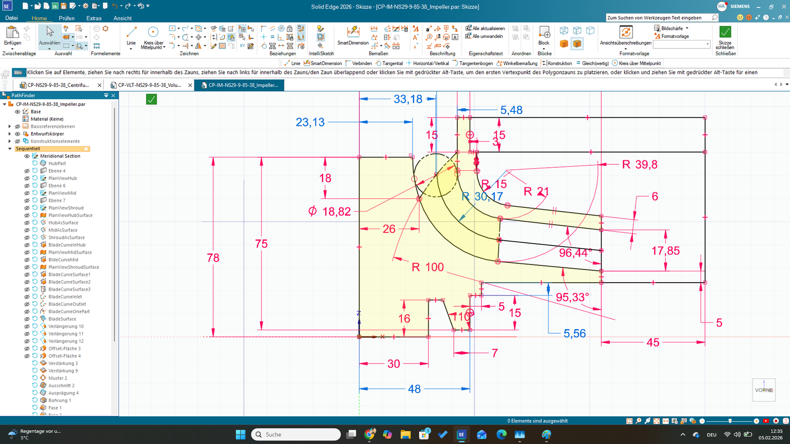
The Excel calculation links the specified duty point to the impeller dimensions and angles. These design quantities define the meridional contour, three-dimensional blade curves and volute cross-sections.
The recording documents a working version with unresolved cell references. The explanations below describe the design process and distinguish specifications, assumptions and calculated quantities.
Duty point and initial parameters
The design starts with a flow rate of 85 m³/h, a head of 38 m and a rotational speed of 2,900 min⁻¹. Water density is taken as 1,000 kg/m³. This gives a metric specific speed nq of approximately 29.12 and a hydraulic power of about 8.81 kW. The head is a design specification; a measured pump curve is not available at this stage.
- Flow rate Q
- 85 m³/h
- Head H
- 38 m
- Rotational speed n
- 2,900 min⁻¹
- Specific speed nq
- 29,12
From flow rate to impeller dimensions
An additional flow allowance for internal leakage is initially included for flow through the impeller. An initial allowance of 5.5% raises the internal design flow to about 89.68 m³/h. Inlet diameter, hub dimensions and available flow area are considered together. In the illustrated design, d1 is about 85.04 mm; the selected outlet diameter is 210 mm and the outlet width is 17.85 mm.
The calculation includes six blades, an outlet metal angle of 16°, and models for blade blockage, slip and hydraulic efficiency. Together, these influence velocities and head. A single selected value therefore cannot replace assessment of the complete design.
Inlet angles and three-dimensional blade geometry
At the inlet, peripheral velocity and flow conditions vary across the passage width. The hub, mean streamline and shroud are therefore treated separately. The ratio of meridional velocity cm1 to peripheral velocity u1 determines the flow angle, to which a 2° incidence allowance is added in the illustrated step. This gives inlet metal angles of approximately 40.82° at the hub, 33.40° at midspan and 27.30° at the shroud.
Each of the three meridional contours is divided into ten segments. The blade angle is varied from inlet to outlet. Segment length and local angle yield a circumferential displacement; with the local radius, this gives the angular increment of the projected blade curve. The calculated points connect the hydraulic design to the three-dimensional blade surface in CAD.
Δu = Δm / tan(β) · Δε = Δu / r
Leakage flows and volumetric efficiency
A separate calculation considers leakage through the annular clearance and flow through six 4 mm balancing holes. Pressure difference, clearance geometry and friction are linked. Reynolds number, friction factor and flow velocity are updated in successive calculation steps.
The model gives approximately 2.26 m³/h through the clearance and 2.30 m³/h through the holes. Together with the useful flow, this yields about 89.56 m³/h internal flow and a calculated volumetric efficiency of around 94.9%. This is a model result under the assumed conditions, not a measured pump efficiency.
Sizing the volute
The volute collects the flow leaving the impeller around its circumference. A selected collection velocity of about 9.57 m/s gives a full reference area of roughly 2,468 mm² in the chosen model. A width-to-height ratio of 1 gives approximately 49.68 mm in each direction.
Worksheet ‘12.28’ distributes the cross-sectional area around the circumference in 30° steps. With Aε = (ε/360°) A360 the assigned area increases with the collected portion of flow. Section height and outer contour radius are derived from the selected width. A 12.28° angular offset and geometric corrections complete the positioning of sections for CAD design.
Preliminary shaft sizing and suction behaviour
Worksheet ‘ShaftDiameter’ relates hydraulic power to shaft power and torque through an assumed efficiency. At 0.77, this gives approximately 11.44 kW and 37.66 Nm. Assumed bending, load factors and a safety factor give an initial strength-based diameter of about 25.86 mm; a 30 mm diameter is selected later in the design. This is preliminary sizing, not a complete fatigue or deflection assessment.
The calculation also estimates NPSHR from a selected suction specific speed. The value of approximately 3.92 m is a design estimate. NPSHA = 8 m is specified in the worksheet. The actual suction installation and subsequent testing require separate assessment.
From calculated values to blade geometry
I divided the blade camber line into ten segments and varied the blade angle from inlet to outlet over these sections. The profile was first constructed on the hub contour and then extended to the shroud contour. The project thus shows how hydraulic design quantities were translated into three-dimensional blade geometry.
Design as an integrated system
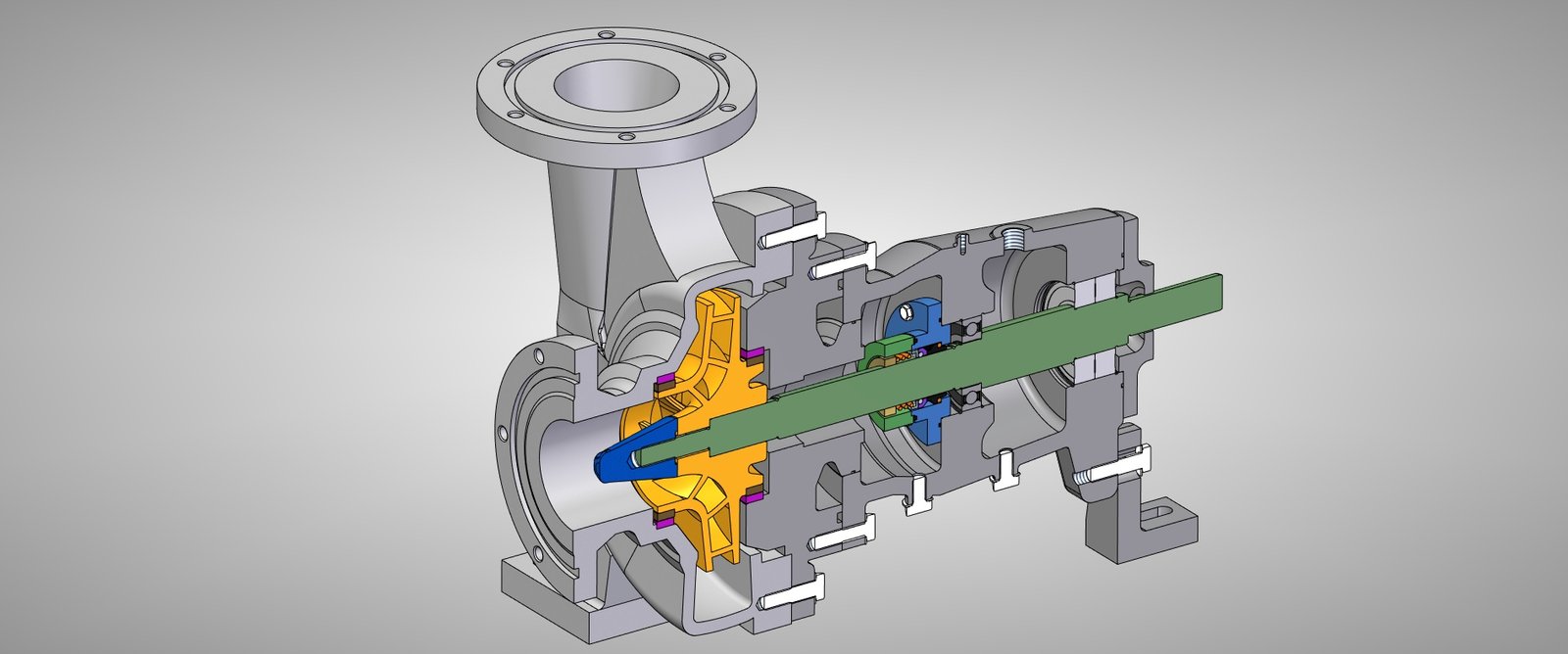
Assembly and exploded views show how the casing, impeller, shaft and associated parts work together. Sections reveal the internal arrangement alongside the external view. Drawing generation links the CAD work to preparation for manufacturing.
Outcome and development status
The hydraulic calculation, 3D assembly and manufacturing drawings are available. The geometry is a detailed initial design. In particular, the relatively large blade wrap angle requires further hydraulic review. No prototype, CFD results or measured performance curves are available at this stage.
What the project demonstrates
The focus is on connecting calculations, CAD modelling and technical documentation throughout the design. The current stage enables technical discussion of the design; experimental verification of pump performance is a subsequent development step.

