
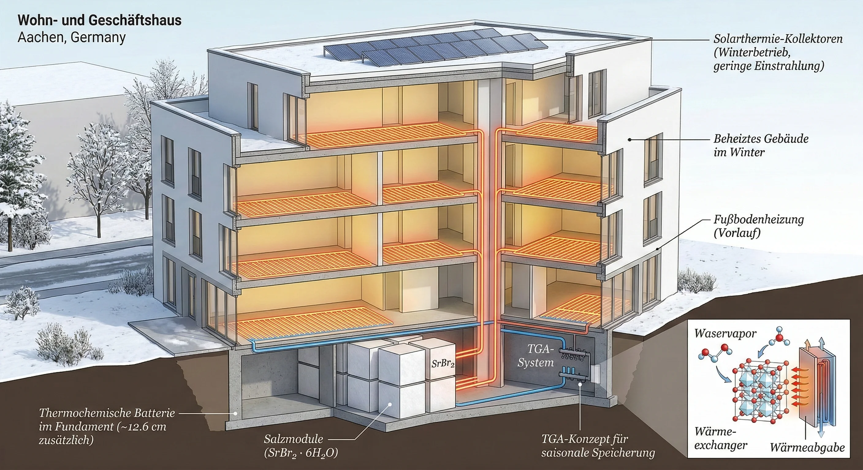
The seasonal mismatch between solar availability and heating demand is a central challenge in building energy systems. Solar radiation is abundant in summer, while space-heating demand is concentrated in the colder months. Seasonal storage aims to retain part of the summer energy for the heating season.
Hot-water tanks store energy by raising the water temperature. Their losses therefore depend on the temperature difference to the surroundings, insulation quality and storage duration. Thermochemical storage instead uses a reversible reaction. Energy can be retained for long periods with limited standby losses when the reactants remain separated under suitable conditions. Charging, discharging and heat transfer still involve losses that must be included at system level. [1]
Contents
How does salt-hydrate storage work?
One investigated approach removes water from a hydrated salt and rehydrates it when heat is required:
- Summer charging: Solar heat removes part of the salt’s water of crystallisation, with management of the resulting water vapour.
- Storage: The reverse reaction is prevented until heat is needed.
- Winter discharge: Water vapour is supplied to the salt under controlled conditions, releasing heat that can be transferred to the heating circuit.
Strontium bromide is among the materials studied. A reaction pair relevant to low-temperature applications is the transition between its hexahydrate and monohydrate forms:
The rightward reaction represents charging and the leftward reaction discharge. The introduction to a study from the German Aerospace Center (DLR) discusses research on this pair for applications below approximately 100–105 °C. It differs from the anhydrous-salt/monohydrate pair investigated experimentally in that study at higher temperatures. Any operating-temperature or energy-density value must therefore be tied to the specific reaction pair and conditions. [2]
Armand Fopah Lele’s A Thermochemical Heat Storage System for Households addresses this pair directly on pp. 62–64. The book relates hydration temperature to water-vapour pressure: evaporation at around 10 °C produces approximately 12 mbar and can allow a reaction temperature near 50 °C under the stated conditions. This is a conditional operating relationship, not a guarantee of constant outlet temperature throughout discharge. [7]
Selecting a suitable material is the start of the design. Actual performance also depends on heat transfer, vapour access to the material, reactor tightness, corrosion resistance and stability over repeated charge/discharge cycles.
Integrating storage into the building
This article proposes investigating dedicated areas near the foundations or in the basement of new buildings for thermochemical storage modules. Providing for this space early in the building design allows larger capacities to be considered without confining the store to a small plant room.
The concept envisages independent, closed reactor modules with access for inspection, maintenance and replacement. The storage material remains separate from concrete and load-bearing elements. Modules can be distributed and connected to a shared thermal circuit according to the building’s requirements.
Low-temperature heating, such as underfloor heating, merits consideration with this concept because the delivery temperature required by the building affects collector and storage operating conditions.
Calculation example: a hypothetical building in Aachen
Aachen, Germany is the reference location for estimating the available solar resource. The building remains hypothetical so that location data and design assumptions are clearly distinguished.
Solar-radiation data
The example uses PVGIS 5.3 from the European Commission’s Joint Research Centre (JRC) and the PVGIS-SARAH3 database. The reference point is 50.7753° N, 6.0839° E within Aachen, with a south-facing surface tilted 45° from horizontal over 2005–2023. The tool provides monthly radiation data for horizontal and tilted surfaces. [3]
Each month was averaged over the 19 years, and the monthly means were then summed into two complementary half-year periods:
| Period | Months included | Incident solar energy on the tilted surface |
|---|---|---|
| Summer half-year | April to September | 878 kWh/m² |
| Winter half-year | October to March | 422 kWh/m² |
| Full year | January to December | 1,300 kWh/m² |
These totals were calculated by the author from PVGIS data and rounded to the nearest kWh/m². The collector calculation below uses an independent hourly series for the same location, period and tilt; its radiation totals agree within small rounding differences. These are incident-radiation values before conversion to useful heat. The query includes the terrain horizon but excludes shading by nearby buildings and trees. [4]
Building and system assumptions and the basis of the efficiencies
| Parameter | Value | Basis |
|---|---|---|
| Building footprint | 1,000 m² | Engineering assumption for the example |
| Heated floor area | 4,000 m² | Engineering assumption for the example |
| Specific annual space-heating demand | 40 kWh/(m²·year) | Example assumption, not a building heat-demand calculation |
| Solar thermal collector aperture area | 700 m² | Assumed reference area for the energy calculation |
| Mean collector-fluid temperature | 90 °C for summer charging; 40 °C for winter heating | Two assumed operating points, not ambient temperatures |
| Equivalent summer collector efficiency | about 41.2% | Calculated hourly from published coefficients and Aachen weather, before distribution losses |
| Equivalent winter collector efficiency | about 54.4% | Same method at the lower operating temperature |
| Reactor output / charging energy | about 72% | Approximate reference from a published simulation; transfer to Aachen requires verification |
The assumed annual space-heating demand follows from:
This gives 160 MWh per year for space heating. The example excludes domestic hot water and electricity for pumps and controls.
The value of 40 kWh/(m²·year) represents a new building with low space-heating demand. Values of 60 and 80 are also tested to show sensitivity to the building’s thermal performance.
Aperture area is the reference area receiving radiation in the collector performance calculation. It is not necessarily the total area required for installation: collector dimensions, spacing, service access and shading affect the required footprint. The example therefore does not assume that 700 m² of aperture can automatically be installed on a roof with a 1,000 m² footprint.
Collector-efficiency calculation. Instead of selecting a constant seasonal efficiency without derivation, the calculation uses the published aperture-area coefficients for the Apricus ETC-30 evacuated-tube collector, technical documentation p. 9: η₀ = 0.714, a₁ = 1.243 W/(m²·K), a₂ = 0.009 W/(m²·K²). [5]
A steady-state approximation was applied to every hour of the PVGIS data from 2005–2023, using the following thermal output per square metre of aperture:
ηseason = Σ(qhΔt) / Σ(GhΔt)
Gh is total irradiance on the tilted surface in W/m², Ta,h the hourly ambient temperature and Tm the assumed mean collector-fluid temperature. Energy was obtained by integrating power over the hours in the period and dividing by the number of years. [9]
This is a screening calculation of collector output, not a complete solar-field simulation. The incidence-angle modifier is set to 1, while collector heat capacity, start-up and pipework/external heat-exchanger losses are neglected. Demand constraints and a full store are not modelled. The resulting efficiencies therefore depend on the model assumptions and must not be presented as measured Aachen performance. These effects must be included when designing a real system. The numerical example further assumes, for simplicity, that collector heat reaches the reactor inlet or heating circuit without additional distribution losses.
Basis of the storage factor. Hennaut et al. (2011) present a TRNSYS simulation of a closed strontium-bromide system in the climate of Uccle, Belgium. Figure 7, p. 5, gives an approximate reactor-output/charging-input ratio of 0.72 for the case with 17.5 m² of collectors and 7,500 kg of salt. It is used here as an approximate reference scenario, not a test result for the hypothetical building. The factor depends on load, store size and discharge state; it is not a fixed salt property. The study assumes evaporation at 5 °C and condensation at 20 °C without detailed modelling of the ground source and evaporator. [8]
This ratio must not be replaced by the 77% efficiency in A Thermochemical Heat Storage System for Households: that indicator relates to peak-power values, pp. 150 and 166, rather than energy recovered between summer and winter. [7]
1. Solar heat available for summer charging
Hourly integration gives an average summer output of 361.245 kWh/m² under the model conditions, equivalent to approximately 41.15% efficiency. For a 700 m² aperture field:
≈ 252,872 kWh = 252.9 MWh
This scenario assumes that the entire amount can be directed to charging, with sufficient capacity and charging power. Summer heat demand, distribution losses or inability to accept the heat reduce the reactor input. Subsequent calculations use the unrounded integration results; the efficiencies in the table are summary values.
2. Heat delivered through the seasonal-storage path
Applying the reference output-to-charging ratio of approximately 72%:
≈ 182.1 MWh
The 72% factor is a scenario based on a published simulation, not a demonstrated seasonal efficiency for the proposed Aachen system. In a closed cycle storing water as a liquid, discharge requires heat to evaporate it. The source and quantity must be identified and separated from the solar energy charged in summer. The result above is total reactor output when that source is available; evaporator heat must not be added again. It cannot establish demand coverage without completing the energy balance and verifying operating temperatures and thermal power over time. [7] [8]
To illustrate this contribution, Table 2.5, p. 36, of the book gives a reference reaction enthalpy of 337 kJ/mol for the hexahydrate/monohydrate pair. Appendix A.3, p. 189, explains subtracting water-evaporation energy when calculating net storage. With approximately 44.6 kJ per mole of water at 15 °C, producing 160 MWh of reaction heat theoretically requires:
≈ 105.9 MWh
This is an order-of-magnitude estimate of low-grade source heat, not a final operating balance. It neglects sensible heat and discharge losses and uses the cited reference values. It does not imply 105.9 MWh of electricity consumption: heat may come from the ground or another suitable source, with its supply requirements accounted for. The same principle appears in the MERITS concept, which uses a different storage material. [6]
3. Solar heat available during the winter half-year
Winter radiation can be used directly for heating or through short-term storage where required. The hourly calculation at a mean fluid temperature of 40 °C gives an equivalent efficiency of approximately 54.39% and an output of 229.591 kWh/m²:
≈ 160,714 kWh = 160.7 MWh
This is potential thermal production at the collector outlet. The amount reaching the building and actually used depends on its timing relative to demand, achievable temperatures, control and additional losses.
4. Comparing annual heat potential with heating demand
Adding the reference reactor output to winter solar heat, within the limits of the simplified calculation:
≈ 342.8 MWh/year
| Item | Approximate annual energy |
|---|---|
| Reactor output in the reference storage scenario | 182.1 MWh |
| Collector output in the winter half-year | 160.7 MWh |
| Total conditional heat potential | 342.8 MWh |
| Assumed building heating demand | 160.0 MWh |
What does this result mean?
Under the selected conditions, the sum of calculated thermal outputs is approximately 2.14 times the assumed annual heating demand. This supports further investigation of the energy potential and suggests scope to reduce collector area or allocate some heat to other uses.
However, 342.8 MWh is a conditional calculated potential. It does not mean the building consumes this amount or achieves a 214% solar coverage fraction. Reactor output includes the influence of the low-grade heat source, so the entire sum must not be described as stored solar energy. Heat used for space heating is limited by actual demand, and an annual comparison alone does not determine the usable surplus.
The winter collector output of 160.7 MWh is itself close to the assumed annual demand. This does not make storage unnecessary: heat may be available on low-demand days while heating is required at other times. It shows that the example tests energy availability with a large collector field rather than determining an optimum system size.
Meeting the heating demand can in principle be investigated when sufficient storage capacity, suitable charging/discharging power, a usable delivery temperature and a source able to supply the evaporator are available. Demonstrating coverage for a particular building belongs in the project study.
Sensitivity to the building’s thermal performance
Keeping the solar field and its calculation conditions unchanged gives the following heating demands and annual comparisons:
| Specific heating demand | Annual demand for 4,000 m² | Conditional heat potential / demand |
|---|---|---|
| 40 kWh/(m²·year) | 160 MWh | 2.14 times |
| 60 kWh/(m²·year) | 240 MWh | 1.43 times |
| 80 kWh/(m²·year) | 320 MWh | 1.07 times |
The values of 60 and 80 are test cases, not standard building classifications. The table shows the annual energy margin shrinking as demand increases, before distribution losses, operating constraints and timing are considered. None of the ratios establishes demand coverage or the required storage capacity. The volume and economic calculations below retain the 40 baseline and must not be applied to the other cases without resizing.
From energy quantity to storage volume
The required capacity depends on how much heat must be shifted between production and demand periods. The store need not equal the full summer production if a smaller capacity can meet the building’s needs. Once the required useful capacity has been established, the general relationship is:
Here energy density means useful heat per cubic metre of the complete system at the required delivery temperature. Theoretical material energy density alone cannot determine the thickness of a store beneath the building. [1]
A volume reference and its limitations
Table 2.6, p. 37, of the book presents the SOLUX prototype based on strontium bromide and expanded graphite. Mauran et al. describe a reactor of 1 m³ and a heating-release capacity of approximately 60 kWh at complete reaction. This example uses 60 kWh per m³ of reactor as a preliminary numerical reference, not a demonstrated whole-system density or a guarantee of useful energy after all losses. [7] [10]
Volume of a store targeting the full annual heating demand
For a clear space-fit test, the initial nominal target capacity is 160 MWh, equal to the annual heating demand, without crediting winter solar heat for reducing capacity. This is a conservative sizing target in terms of energy to be shifted, not an estimate of the minimum required capacity. The reference reactor volume becomes:
≈ 2,667 m³
Space is also required for water, the evaporator, condenser, connections and maintenance access. To estimate the minimum exchanged liquid-water volume, the calculation uses the five-water-molecule reaction and the 337 kJ/mol enthalpy from Table 2.5 of the book:
≈ 154,000 kg
Vwater,min ≈ 154 m³
This is water alone at approximately 1,000 kg/m³, excluding vessel walls and ullage. It is not included in the reference reactor volume used here.
For architectural comparison only, 20% of the total space is reserved for ancillary equipment, access and maintenance, leaving reactors and water to occupy 80%. This is an explicit planning allowance, not an experimental result or a value taken from the book. Its adequacy must be checked once equipment has been selected:
≈ 3,526 m³
hequivalent = 3,526 / 1,000 ≈ 3.53 m
Using the full 1,000 m² footprint at an assumed clear height of 3 m gives 3,000 m³, less than the approximately 3,526 m³ reference estimate. Even the reactors alone require an equivalent volumetric height of about 2.67 m. A shallow space beneath the foundations therefore cannot meet this target at the reference reactor density. Equivalent height is a volume-to-area ratio; it does not establish that equipment can be arranged or accessed in practice.
What if the required seasonal capacity is smaller?
| Nominal target capacity | Reference reactor volume | Minimum water volume | Space including planning allowance | Equivalent height over 1,000 m² |
|---|---|---|---|---|
| 40 MWh | 667 m³ | 38.5 m³ | 881 m³ | 0.88 m |
| 80 MWh | 1,333 m³ | 77.0 m³ | 1,763 m³ | 1.76 m |
| 160 MWh | 2,667 m³ | 154.0 m³ | 3,526 m³ | 3.53 m |
A smaller capacity might therefore fit volumetrically within a basement. Establishing whether 40 or 80 MWh is sufficient nevertheless requires a time-resolved production/demand balance. Required capacity cannot be found by subtracting annual winter production from annual load: surpluses and deficits can occur in different months and on different days.
A 160 MWh output target requires approximately 222.2 MWh of charging heat at the reference ratio of 0.72, compared with 252.9 MWh at the summer collector outlet. This leaves an energy margin in the simplified scenario, reduced by distribution losses and other uses. Reactor volume is not multiplied by 0.72 again: the ratio relates output energy to charging energy, not volumetric occupancy.
These remain preliminary nominal volumes, not an implementation design. Incomplete reaction, inability to recover all heat at a useful temperature, and losses in delivery to the building may increase the volume needed. The volume reference and energy ratio also come from different studies; combining them for a preliminary comparison does not demonstrate that both can be achieved in one reactor. Equipment/material masses and loads, evaporator and source capacity, access and maintenance must all be checked.
Annual savings and economics compared with gas heating
Energy availability alone does not establish viability. Collector, reactor, material, heat-source and construction costs must be compared with fuel purchases actually avoided, after electricity, maintenance and replacement. The following is a preliminary economic screening using reference prices, not a quotation or final investment study. The baseline remains 160 MWh of annual space heat. Amounts include VAT, and actual quotations must be compared on the same tax basis.
What does supplying this heat with gas cost?
The local reference is Aachen’s published STAWAG Gas Extra tariff for annual consumption of 12,001 kWh and above: 11.38 euro cents/kWh of gas, including VAT. The September 2026 price sheet, valid from 1 January 2026, also gives an annual fixed charge of €184.09. This is a local reference at the review date, not a guarantee of the contract price over the project lifetime. [11]
The gas system is assumed to have a 90% seasonal efficiency on the billed gas’s higher-heating-value basis, Hs, from purchased gas to useful space heat. This comparison assumption must be checked for the actual alternative and must not be confused with an instantaneous efficiency or one based on lower heating value. This gives:
Cgas,variable = 177,778 × 0.1138 ≈ 20,231 €/year
Including the fixed charge gives a reference bill of approximately €20,415 per year. The fuel saving below uses only the variable consumption charge, since the fixed charge may remain if gas is retained for peak loads or domestic hot water. Taxes and levies already included in the tariff are not added again.
How much saving can be attributed to the new system?
Savings are based on useful heat that actually replaces gas, not the total 342.8 MWh potential. Let f be the heating-demand fraction met by the solar-plus-storage system, including the influence of its low-grade heat source:
Snet = Sfuel − ΔCoperation
ΔCoperation covers net additional annual operating expenditure compared with gas: electricity for pumps, controls and vacuum generation where needed, evaporator heat, inspection, maintenance and provision for component or material replacement, after crediting maintenance avoided on the alternative. It cannot be calculated from the 0.72 ratio alone.
To show the effect, assume €5,000 per year of net additional expenditure as a test case. This is a calculation allowance, not an operating quotation, and must be replaced with actual equipment values in a project study:
| Heating coverage test case | Heat replacing gas | Annual gas-purchase saving | Net saving after €5,000/year |
|---|---|---|---|
| 50% | 80 MWh | €10,116 | €5,116 |
| 80% | 128 MWh | €16,185 | €11,185 |
| 100% | 160 MWh | €20,231 | €15,231 |
These fractions are economic scenarios, not coverage fractions demonstrated by the technical calculation. Actual coverage requires a time-resolved simulation and verification of power and temperature. At gas efficiencies of 85% and 95%, full-coverage fuel savings become approximately €21,421 and €19,166 per year respectively.
For evaporator sensitivity, if all 160 MWh of space heat passed through storage, the previously estimated 105.9 MWh of ideal evaporation heat means that each additional euro cent per kWh of source heat adds about €1,059 per year. This tests the cost of heat provision. It is not added again if already included in the operating allowance, and the evaporator quantity falls when winter solar heat meets part of the demand directly.
Investment cost and payback
The relevant measure is additional investment compared with an alternative providing the same function, ΔI. It includes collectors, reactors, salt, water management, heat source, vacuum equipment, controls, installation, design, construction and dedicated space, subtracting only alternative investment genuinely avoided. If a backup boiler must remain, its cost is not automatically avoidable.
This calculation assesses the complete solar-plus-storage solution against gas. The whole saving must not be attributed to the battery alone, since collectors also supply direct winter heat. Assessing the battery addition itself requires comparing the same solar field with and without seasonal storage, using the extra gas saving enabled by storage against its additional cost. That time-resolved comparison has not yet been performed.
No system quotation is available for the example, so no invented number is presented as an actual installation cost. Instead, three additional-investment values are tested, assuming full coverage and net savings of €15,231 per year:
| Illustrative additional investment | Simple payback |
|---|---|
| €300,000 | about 19.7 years |
| €500,000 | about 32.8 years |
| €1,000,000 | about 65.7 years |
The investment values are not market prices for the store, and simple payback ignores the time value of money. A 20-year horizon and a 3% annual real discount rate are therefore also tested, with constant real prices and performance and no grants or residual value. Lifetime and discount rate are appraisal assumptions, not a demonstrated operating life. Major replacements must be included if not covered by the operating reserve. The present value of savings is:
r = 0.03; N = 20; factor ≈ 14.877
| Assumed coverage | Maximum additional investment matched by 20 years of savings, present value |
|---|---|
| 50% | about €76,100 |
| 80% | about €166,400 |
| 100% | about €226,600 |
Under full coverage and the assumed operating expenditure, additional investment would need to be about €227,000 or less to be matched by 20 years of savings at a 3% discount rate. Even €300,000, which has a 19.7-year undiscounted simple payback, is not recovered within that discounted horizon. Assuming zero additional operating costs raises the ceiling to about €301,000, an idealised comparison case.
Gas price also matters: at 8 or 15 euro cents/kWh instead of 11.38, full-coverage fuel savings would be approximately €14,222 or €26,667 per year. These are sensitivity cases, not forecasts of future gas prices.
What does this imply for future implementation?
The economic conclusion is conditional, not proof of profitability. Potential annual gas savings are limited by actual building demand; abundant energy alone does not justify a large store. The 3,526 m³ reference space for 160 MWh makes integration harder and may add construction and opportunity costs for the space. Investment decisions require a complete cost quotation, demonstrated coverage and a lifetime assessment of operation and replacement.
Implementation challenges include tightness at low pressure, heat and vapour transport within the salt, corrosion, agglomeration, volume change, evaporator-source control and maintenance access. The IEA SHC update published in April 2025 identifies scaling production, translating performance requirements into component design and high costs as continuing challenges for compact thermal storage in general. This is a sector-level assessment, not a claim that all thermochemical-material applications have the same maturity. [12]
Future applicability improves if standard modules demonstrate higher useful whole-system density, lower manufacturing and installation costs, and a reliable life with limited maintenance and an inexpensive low-grade heat source. Repeated annual use can spread investment over more energy but must be demonstrated for the operating pattern. A seasonal store with one annual cycle differs economically from a frequently cycled store. On the current evidence, the proposal is best treated as a feasibility-study and pilot-project topic with testable economic conditions, before describing it as a ready, economical replacement for gas heating. Later comparisons should include better insulation, heat pumps, short-term storage or shared heating on the same lifecycle-cost and thermal-comfort basis.
What needs further development?
Moving from this concept to practical implementation requires four connected areas to be coordinated:
- Material and reactor: cycle stability, heat and vapour transfer, charging/discharging rates and chemical compatibility with reactor construction materials.
- Thermal system: operating temperatures, collector efficiency, losses, management of water, vapour and evaporator-source heat, and heat-distribution control.
- Building integration: actual volume and equipment/material masses, access, maintenance, replacement and separation from structural elements.
- Economics: material, module, installation and operating costs compared with alternative heating and storage solutions providing the same function.
The Aachen data give the concept a clear geographical basis and show how results change with collector area, system performance and available capacity. The core engineering idea remains to use early building design to provide suitable seasonal-storage space, then develop the system around heat, space, maintenance and cost requirements together.
References and data
- IEA SHC — Task 67, 2022 Highlights. Compact thermal storage and the transition from material properties to component and system performance. Original PDF
- Stengler, Bürger & Linder — DLR. Thermodynamic and kinetic investigations of the SrBr₂ hydration and dehydration reactions for thermochemical energy storage and heat transformation. The citation refers to the introduction, p. 2, discussing the monohydrate/hexahydrate pair; high-temperature-pair experimental results are not transferred to this example. Original PDF
- European Commission, Joint Research Centre — PVGIS. Explanation of monthly radiation data, units and reference surface types. Original source
- PVGIS 5.3 / SARAH3 — Aachen example data. Coordinates 50.7753, 6.0839; 2005–2023; 45° south-facing tilt; retrieved 25 October 2026. Seasonal table values are the author’s aggregations of monthly means. Data query
- Apricus — ETC Solar Collector Product Overview, September 2016, pp. 9–10. Collector-area definitions, efficiency curves and incidence-angle effects. ETC-30 aperture-area coefficients were used in the hourly screening calculation. Seasonal efficiencies are this article’s results under its assumptions, not seasonal values published in the document. Original PDF
- IEA Energy Storage — Annex 33, final report, May 2021 revision, p. 249 (PDF page 250). MERITS concept, water management and low-grade heat source in a closed storage cycle. MERITS uses a different material; the citation supports the vapour-management principle, not strontium-bromide performance. Original PDF
- Armand Fopah Lele — A Thermochemical Heat Storage System for Households: Combined Investigations of Thermal Transfers Coupled to Chemical Reactions. Springer Theses, 2016. DOI: 10.1007/978-3-319-41228-3. Relevant passages: p. 36, Table 2.5; p. 37, Table 2.6; pp. 62–64; pp. 150 and 166; Appendix A.3, pp. 189–190. Page numbers are the book’s printed pagination. Publisher page
- Hennaut, Thomas, Davin & André (2011). Dynamic simulation of residential buildings with seasonal sorption storage of solar energy – Parametric analysis. University of Liège, ISES Solar World Congress. System conditions on pp. 2–3; reactor-output/charging-input ratio in Fig. 7, p. 5. Approximate graphical reading for 17.5 m² and 7,500 kg, not a measurement of the Aachen system. Original PDF Original source
- European Commission, JRC — PVGIS 5.3 / SARAH3, hourly series. Same coordinates, tilt and period as reference 4; 166,536 records; retrieved 26 October 2026. Tilted-plane radiation components and ambient temperature were used. Original source Data query
- Mauran, Lahmidi & Goetz (2008). Solar heating and cooling by a thermochemical process. First experiments of a prototype storing 60 kWh by a solid/gas reaction. Solar Energy 82, 623–636. Reactor volume and capacity at complete reaction are used as an initial sizing reference; also presented in reference 7, p. 37. Publisher page
- STAWAG — Gas Extra, September 2026 price sheet, p. 1. Valid from 1 January 2026 for annual consumption of 12,001 kWh and above: gross consumption price 11.38 euro cents/kWh and fixed charge €184.09/year, both including 19% VAT. Checked 26 October 2026. Original PDF Original source
- IEA SHC — Task 67: a worldwide effort in advancing compact thermal energy storage. Update published 14 April 2025 on production scaling, component design, costs and market transition in compact thermal storage. Original source
Building dimensions, operating temperatures and the space allowance are explicit choices for the example. Collector coefficients are published references and seasonal efficiency is calculated from hourly data; reactor output ratio and volumetric capacity come from different references and are used for preliminary comparison. The economic analysis uses a published tariff and explicit coverage, operating and investment assumptions; it includes neither an actual cost quotation nor a savings guarantee. The results are not design approval or proof of coverage. The calculation record, data and method are attached for review and reproduction.